 This article was submitted to HamRadioSchool.com by Al Andzik WBØTGE. It describes a unique copper pipe fan dipole that Al created and that provides fantastic results! Thanks for the submission, Al!
If you have an article that you’d like to submit for consideration, please see our submission guidelines in our ‘contact us’ link. We’d love to hear from you!
I call this the “Mighty Woof” antenna. It reminds me of two “Wouff Hong” antennas (created by Hiram Percy Maxim) joined together at the base and creating an awesome signal.
The W0TLM 2013 fall tech day had many great displays and instructional sessions for club
members. I watched a presentation by Bob Witte, KØNR, which discussed the many types of antennas available to amateur radio operators and the benefits each antenna design provides. It was an excellent technical presentation.
One of the antennas Bob discussed was the HF wire fan dipole. This is a multi-band antenna
which gives the amateur the capability of utilizing several radio bands with only one feed line. The fan dipole is usually constructed of multiple sections of wire tuned for each band required.
That night at home the thought struck me that the fan dipole could be used for the VHF/UHF bands. I like building antennas from copper pipe and have made many j-poles for myself and others. I did an online search for copper pipe fan dipoles and found none. Was it because they didn’t work? Well that became a challenge. The design presented here was developed empirically by using cut and test methodology with SWR measurements being made after each adjustment.
The antenna is constructed using 1/2” copper pipe and copper fittings. Cost was under $25. The center section utilizes a 1/2” NIBCO CPVC SxSxS Tee purchased at Home Depot. This plastic tee inside diameter matches the outside diameter of 1/2” copper pipe.
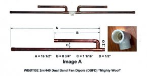
Construct two half sections of the dipole using the dimensions in the following image (Image A.
As you cut the copper pieces fit them together and measure the result. Measure with the end caps on the ends of the two long sections. The end caps are included in the finished dimensions. Cut each piece of copper pipe a little long initially so that you can trim to fit the finished dimension later. This is necessary because copper fittings vary in dimension between manufacturers. Use a 7/8” length piece of copper pipe to butt join the elbow (for the shorter 440 MHz elements) to the tee at the base of the dipole half. Also the piece on the bottom of the dipole half should not extend more than 1/2” from the tee (Dimension “D”).
When you purchase the 90 degree elbows find the most compact sizes. This will allow the elbows to be butt soldered to the tees for the proper center dimension of the fan dipole without having to trim one or both of the elbows to make them shorter.
 After all of the pieces have been cut/trimmed, fitted together and measured, solder the pieces using lead free solder and flux.
(NOTE: I know there are discussions that plumbing flux should never be used on electronics, however, this is not electronics it’s plumbing, so don’t worry. This soldering method is what is needed for the outside use of these antennas. Wear protective clothing, work in a well ventilated area, and observe proper safety precautions whenever soldering
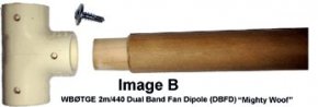
Looking at Image B, drill three 1/8” pilot holes on one side of the plastic tee about 1/4” from the ends of the openings. The image shows the 1/2” self-tapping screw used and the hardwood dowel used as the the mounting mast for the antenna. Sand the dowel end to match the inside diameter of the tee. Make it a press fit and long enough to seat completely into the tee opening. The copper pipes and wood dowel are secured to the tee using the self-tapping screws.
Both soldered dipole halves needs to be driven into the plastic tee fitting. If you look at Image A, inside the tee on each hole is a ledge about 1/2” down inside. This ledge is where the dipole half’s rest when the antenna is assembled.
 Take the two dipole half’s and insert them into opposite sides of the tee. Orient the tee so that the center hole is facing opposite the two shorter elements per Image A
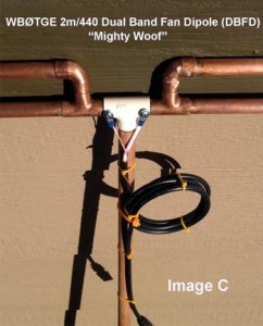
Place one end of the antenna on a piece of wood, using another piece of wood for protection, tap the other dipole end and force the dipole halves into the tee until both are seated completely, the copper pipe of each half resting on the interior ledges of the plastic tee fitting. Secure the plastic tee to each dipole half using ½” self-tapping screws through the previously drilled holes and into the piece of copper pipe, as shown in Image C. The screws will drill into the copper pipe without pre-drilling the pipe. Don’t over-torque the screws. Attach the dowel also with a self-tapping screw. It is important that the screws “screw” into the copper pipe for connection of the coax.
(NOTE: If self-tapping screws are not available, pre-drill a small hole for the size screw available. Use the holes drilled in the plastic tee for a guide since the copper pipe is already seated in the tee.)
Now you are ready to attach the coax to the antenna (Image C). Separate the shield from the center conductor insulation for a distance of about 2-3 inches. Solder appropriately sized ring terminals to each of the coaxial cable center conductor and shield. Take out the screw attaching each of the dipole halves to the tee and attach the coax to the antenna by re-inserting the screws through the two ring connectors, one to each half of the dipole. It doesn’t matter which wire goes to which side. You may wish to protect the screws by applying a silicone sealer to prevent oxidation, and you may wish to cover the coax attachment area with rubber electrical tape or moisture protection sealant that conforms to the shape of the tee. This will help prevent moisture intrusion into the coaxial cable or potentially shorting the two halves of the dipole.
INTERESTING VIDEO

Share this Post
latest post
-
 Ham Radio Manufacturers June 25, 2026
 -
 Ham Radio battery backup June 15, 2026
 -
 Amateur Radio Internet June 5, 2026
 -
 Amateur Radio pictures May 26, 2026
 -
 Linux Ham Radio Software May 16, 2026
 -
 Baltimore Amateur Radio Club May 6, 2026
 -
 Ham Radio Packet Software April 26, 2026
 -
 Ham Radio General Class Study Guide April 16, 2026
 -
 Amateur Radio gear March 31, 2026