Greg VE3NXB Having used simple wire dipoles and verticals for many years, I have found that too many of my great expectations were in reality, just duds. As I get wiser... well hopefully, I realize that some well worn antenna configurations are the easiest and loudest lash-ups tried so far. Strangely, few antenna gurus tell the whole story, but that has changed of late. OK, so what's so great about this antenna? Well actually a family of antennas were you pick the configuration that suits your immediate need, like field day, or QRP at the campground. How about:
OK, now what's the down side?
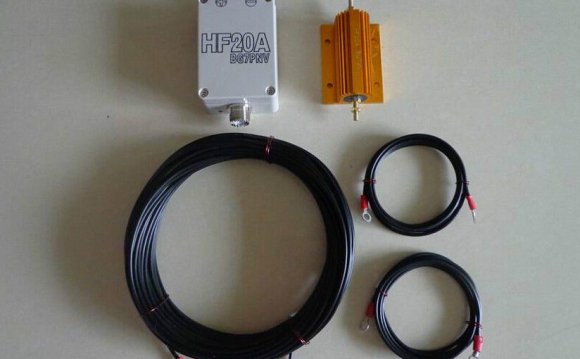
In a nutshell, each antenna is an end fed (high impedance) wire of at least one-half wavelength and configured as a vertical dipole, inverted ground plane, half square, or bobtail curtain. They all use the same parallel resonant impedance transformer to create about 4, 000 ohms at the feed point. The vertical dipole or inverted ground plane has an omni-direction pattern, low take off angle, and low loss. The half square or bobtail, has bi-directional broadside gain with pattern nulls in the opposite directions. The impedance transformer usually rests on the ground where it connects to the co-ax feed line and an end of the antenna wire (see figure). Ground the co-ax shield to a short ground stake at this point. You can achieve the bang of a horizontal dipole at a one half wavelength height (required for low angle DX performance), at half the physical height when you configure your wire as a half square. But, if you have the space, add more wire (remember, same physical height) and make a bobtail. The pattern azimuth curves narrow, the nulls off the horizontal ends deepen, and the broadside gain jumps. An impedance transformer set to resonance drives any of these antennas. I made mine from 10.5 feet (3.25m)of 12 AWG solid copper bare wire. Make the coil inside diameter about 1.5 inches (4cm). Evenly space windings the width of the wire. For low power operation, almost any air variable capacitor of at least 30 pf can be used to resonate on the 30 or 20 meter band. The 50 ohm co-ax tap will be found at approximately one quarter of the total number of turns as measured from the bottom. Too keep mine dry, I mounted the circuit in an inverted plastic ice cream container with the snap-on lid screwed to a wooden plank for stability. The plank and the co-ax rest on or at ground level. To create a "no tune" installation at your site, pre-resonate the transformer on the bench. Temporarily place a 4 to 4.5 K ohm, one watt or greater carbon resistor between the top and bottom of the coil. This is a dummy load. Connect an antenna analyzer to the co-ax feed point. Set your frequency on the analyzer and adjust the capacitor for minimum SWR, then adjust the tap point for 1:1. When you finish your antenna installation, the transformer will still show a nicely matched impedance on the co-ax. If not, you measured your wire incorrectly. Note that the very high impedance at the top of the coil will vary considerably if your hand, metal, or something like a tree branch comes close. Using moderate to high power creates very high RF voltage, so protect people and animals from contact. To determine length for 12 AWG insulated wire, use the following formulas:
The formulas differ from the norm for the half square and bobtail to maintain a close match to the impedance transformer and be somewhat inductive. This positions the array for optimum gain as described by L. B. Cebik, W4RNL in his article, "Power and Antenna Gain on 60 Meters" that appears on page 36 of the February, 2004 issue of QST magazine. Although Cebik presents his antenna data using the new American 60 meter band, it is applicable to all. Here you will also find gain figures and comparisons for these antennas. His work illustrates the performance achievable. |
INTERESTING VIDEO


Share this Post
latest post
-
 Ham Radio Manufacturers June 25, 2026
 -
 Ham Radio battery backup June 15, 2026
 -
 Amateur Radio Internet June 5, 2026
 -
 Amateur Radio pictures May 26, 2026
 -
 Linux Ham Radio Software May 16, 2026
 -
 Baltimore Amateur Radio Club May 6, 2026
 -
 Ham Radio Packet Software April 26, 2026
 -
 Ham Radio General Class Study Guide April 16, 2026
 -
 Amateur Radio gear March 31, 2026